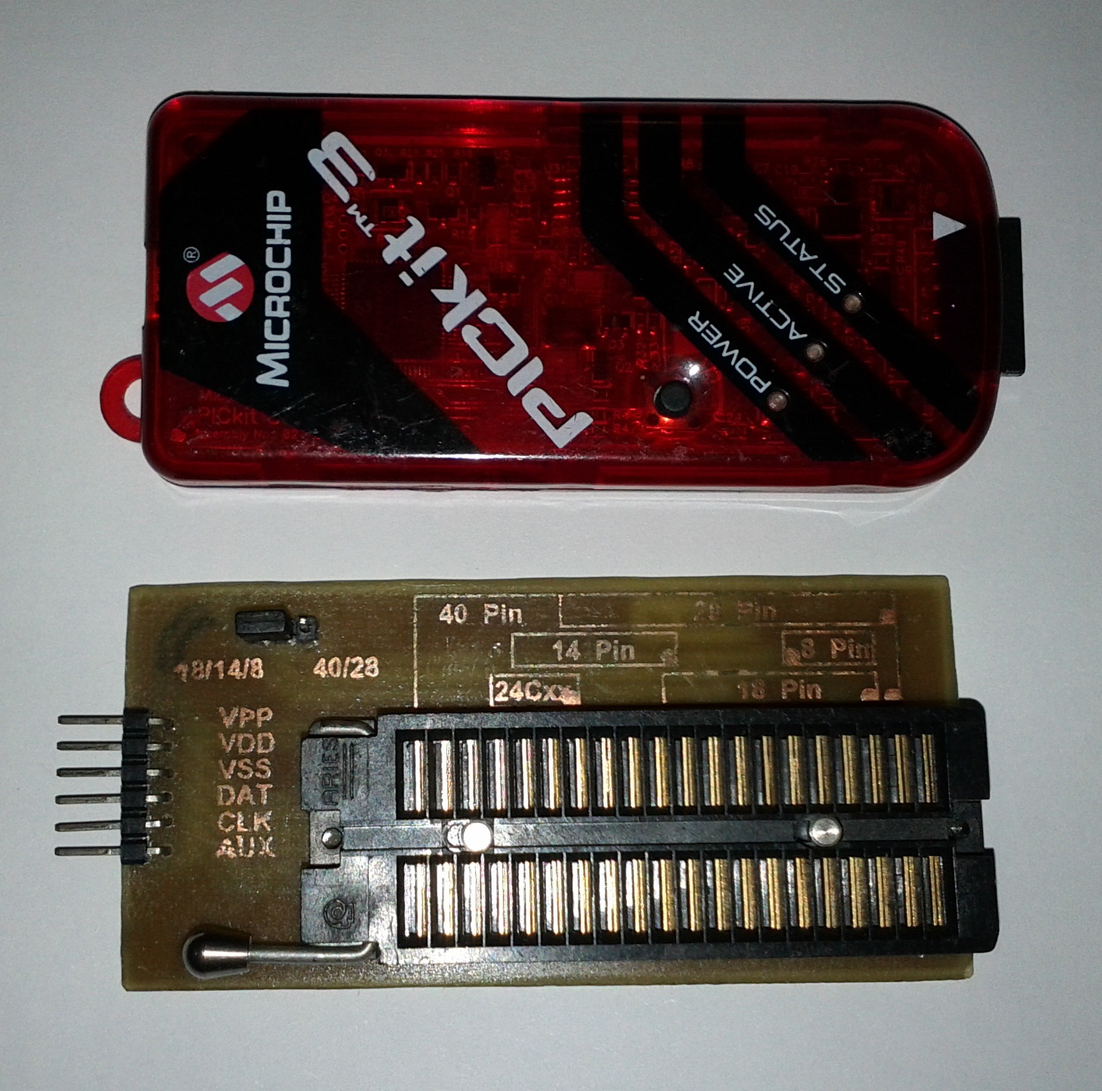
Years ago, when I started with Microchips microcontrollers, I made my first JMD programmer, it was a serial port programmer and it had a bunch of sockets of different sizes in which I just to place the PIC to be programmed, but I couldn´t use it with my laptop because they don´t come with serial ports any more, so I bought a Pickit 2 and let me just say that it is the best programmer money can buy. In the down side it does not have any sockets because it is intended to use the ICSP method and been a rookie I needed sockets, so I started to design a PCB that it will plug directly to the Pickit and before I could finished I found the Winpic800 programmer. this programmer has a 40 pin zif socket on top where pics from 40 to 8 pin can be programmed. I thought that is was a great solution instead of a bunch of sockets. Luckily the guys from Winpic800 give there schematics for free and I just needed to adapt there schematics to fit directly to the Pickit connection and this what I came up a few days later.
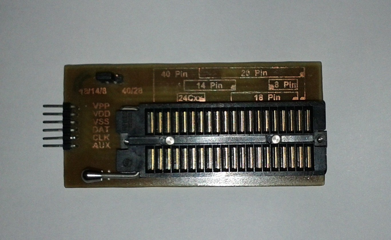
It is almost the sizes of the Pickit and it has a jumper to select between 18/14/8 and 28/40 pin PICs. plugs directly to the Pickit and it is small enough to fit in a pocket. It has 5 jumper wires underneath the zif. To use it just select the number of pins with the jumper and place the PIC according to the drawing and it numbers of pins.
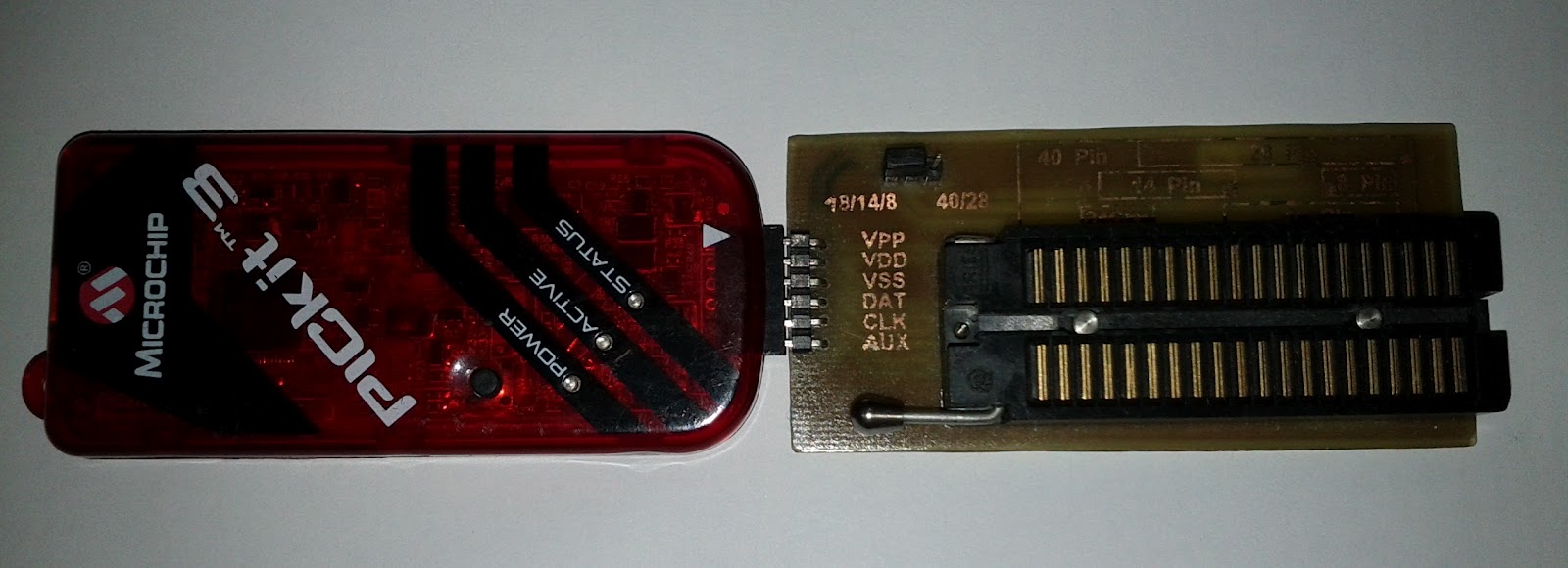

Now I have the Pickit 3 because my Pickit 2 got stolen, but it proof that it is compatible with any of them. I have successfully tested it with several PICs and here is a small list of then:
- PIC16F871 (40 pins)
- PIC16F877A (40 pins)
- PIC18F4550(40 pins)
- PIC16F870 (28 pins)
- PIC16F876A (28 pin)
- PIC16F873 (28 pins)
- PIC18F2550 (28 pins)
- PIC16F88 (18 pins)
- PIC16F628A (18 pins)
- PIC16F688 (14 pins)
- PIC16F675 (8 pins)
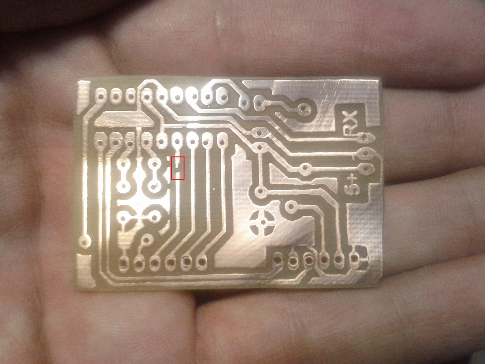
Zif PCB
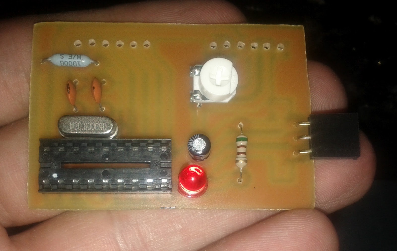
Silk screen